
Since 1923, we have been a part of many vibrator installations on hoppers and bins. One of our major markets is supplying industrial vibrators to the feed and grain industry. I have spent time talking to and visiting folks who ensure their facility operates efficiently with minimal downtime. During those visits, I’ve come across many unique techniques to mount a vibrator on a bin or hopper—specifically, the installation and types of channels and mounting brackets.
Where should you install your industrial vibrator?
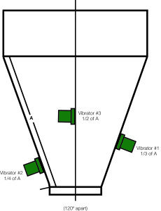
Even if the installation doesn’t fit the standard mounting practices, our installation manuals are still helpful. In most cases, we suggest mounting the vibrators on the sloped section of the hopper or bin about one-third of the way up from the discharge. If using two vibrators, we recommend spacing them 180 degrees apart. If using three, we recommend 120 degrees apart. Staggering the vibrators will maximize the effect on the bin walls to assist in material flow.
The standard locations would be 1/3 up from the discharge for the first unit, 1/4 way up from the discharge for the second unit, and 1/2 the way up from the discharge for the third unit. (See Diagram Below)
This seems to create the best material flow situations in most of our applications. For these installations, we have standard mounting channels available. You can also add angle runners or request longer transmission channels if necessary. Sometimes you may need to add a reinforcement plate to the hopper or bin wall. This will strengthen the wall prior to welding on the mounting channel. The Cleveland Vibrator Company can also furnish this upon request. We typically recommend a 24″ square, but we can supply a different size if applicable to your unique operation.
You can learn more about the proper placement and installation of your pneumatic vibrator in this blog from vibration expert Mike Stratis.
Sometimes we encounter issues pertaining to wall damage because of the use of vibratory aids on the hopper or bin. Yes, it happens, but the damage doesn’t come from the vibrator itself. Damage often stems from improper installation.
There are several potential causes for wall damage:
1. The wall thickness is too thin to support the weight and force of the industrial vibrator.
If the industrial vibrator is properly sized, you can fix this issue by adding a reinforcement plate.
2. The reinforcement plate uses a continuous weld.
This will not allow the plate to properly flex the walls during vibration. It will also cause issues by concentrating too much vibration in one area. Instead, during installation, stitch weld the reinforcement plate and be careful not to weld the corners.
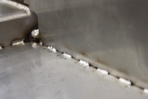
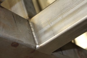
(Example of a Stitch Weld) (Example of a Continuous Weld)
(Photo Credit: Vista Industrial Products, Inc.)
3. The mounting channel is continuously welded to hopper-bin wall or reinforcement plate.
This would have the same installation and welding fix as item number 2.
4. Operating pneumatic vibrators at too high of air pressure or rotary electric vibrator at too high of a force setting.
We recommend operating the air vibrator at 60 psi using an air regulator. Operating at straight plant air could be upwards of 100 PSI or more. This will put unneeded stress on the wall and shorten the life of the vibrator.
Uras Techno rotary electric vibrators are preset at 40% of the unit’s max force. We started doing this several years ago to help prevent hopper or bin wall cracking. It also allows our customers to increase the force of the vibrator as needed.
5. Not providing a controlled run time for your industrial vibrator.
Too long of a run cycle can stress the hopper walls and cause the material to compact instead of flow. I don’t know of any magic set run time, but plant managers and maintenance supervisors frequently mention 3 to 5 minutes as their cycle on time.
Besides manufacturing industrial vibrators, we also manufacture vibratory equipment. This gives us a pretty good working knowledge of welding brackets and channels. I have always recommended using a Lincoln welding rod to weld brackets on hopper bins. We used Low Hydrogen 1018 -1/8″ as a guideline and realized that other electrodes and welding wire work just as well.
Here are a few unique hopper and bin vibrator installations I’ve encountered in the field:
Perimeter channel welded around the feed hoppers.
One of the first feed mills I ever visited had welded a perimeter channel completely around the feed hoppers about 2/3rds of the way up the slope section and installed vibrators there. This approach seemed to work pretty well, but they still needed some vibrators mounted closer down toward the discharge to ensure optimal material flow. I thought the perimeter approach was a great way to transmit vibration along a 360-degree diameter.
Diagonally installed mounting channel.
I visited another feed mill that had purchased several new hoppers with channels welded diagonally on the hopper walls. I wasn’t sure why and asked the plant manager what was the reason for welding channels in this manner. He thought they were installed as impact points for when they had to hit them with hammers to help the material flow. We quoted air piston vibrators to replace the need to hammer on the bins. We recommended the installation of air piston vibrators because they provide a linear vibration that allows mounting from several angles. If the customer had gone with a rotary electric option, they would have had to reinstall the mounting channels.
1350 VMRR Rail Car Vibrator installed on a large feed mill hopper.
The third and most unique application involved our 1350 VMRR rail car vibrator and a rail car wedge bracket mounted on a large feed mill hopper. The sloped section of the feed hopper was roughly 16 ft. to 18 ft. high and was flanged at that point to the straight wall, which extended several more feet upwards. The customer took the rail car bracket and welded it where the sloped section and straight wall were flanged and then dropped the 100-pound vibrator in the bracket at that point. It was exciting to see what is typically used on a rail car hopper hanging several feet in the air on the side of a feed hopper. The customer said it worked, and although we quoted them vibrators with more conventional mounting, they are still using it. The adage, “if it ain’t broke, don’t fix it” must apply here.
These are only a few examples that prove that though textbook installations are great, improvising works too. Every application is unique, and our customers are surely creative when it comes to mounting vibratory aids.
Remember, we are here to help! Our vibration experts are ready to answer any question you may have regarding proper installation.
Do you have a unique installation of one of our products? We would love to see it! Contact us to learn how you can earn FREE Cleveland Vibrator Company swag and have your photo featured in our application gallery.
Share this blog post:
Follow us: