
Once again I’m touching on the topic of the proper setup of rotary electric vibrators (RE) when they’re used on vibratory equipment. Most of the vibratory equipment manufactured by The Cleveland Vibrator Company uses two rotary electric vibrators to produce linear vibration. Vibratory tables (FA), vibratory grid tables (GT), electromechanical screeners (EMS) and electromechanical feeders (EMF) are all designed for the vibrators to counter rotate. Again, counter rotation simply means that the vibrators rotate in different directions, one clockwise and the other counter clockwise. It doesn’t matter which vibrator of the pair rotates clockwise or counter clockwise, it’s just important that they both don’t rotate in the same direction.
I recently tagged along with Jack Steinbuch on a visit to a customer who was experiencing some problems with a vibratory hopper feeder (RFM). After inspecting the unit we asked the customer to remove the weight covers on the vibrators so we could check the rotation direction. Once the weight covers are removed from the same end of each vibrator it’s very easy to see the direction of rotation as the vibrators are started up. At startup it was clear that the vibrators were NOT counter rotating as required. Unfortunately for the customer, the lack of counter rotation was at the core of the problems with the unit, something that could have been easily resolved after the installation of the equipment and at the initial startup.
There are a couple of very easily identifiable indicators that the vibrators are both running the same direction:
- Slow movement of the material from the inlet end to the discharge end.
- Material will tend to move to one side of the unit on vibratory screeners or feeders. With counter rotating vibrators, material will essentially stay in “its lane” as it travels the length of a piece of equipment. Where the material lands on the vibrating surface, it will tend to stay in that location relative to the sides as it moves down the screener or feeder. When the vibrators run in the same direction the material will move to one side of the unit.
- When viewed from the infeed or discharge end, there will be some side to side motion present in the equipment. With properly set up rotary electric vibrators, there is no side to side motion in a feeder or screener, the only motion is end to end.
On the piece of equipment Jack and I saw on our visit, it was a bit more difficult to observe some of these indicators. The unit is fairly tall; to actually view the vibratory feeding surface you need to stand on a ladder. Additionally, the customer’s feed rate is rather low, so even if the material was moving to one side and not feeding as quickly as designed, for this application the task was still being accomplished.
As a resource for our customers I thought it might be a good idea to video and illustrate the concept of counter rotation on a unit here in the plant prior to shipping it out to the end user. First we’d run the unit with the proper counter rotation of the vibrators and then, change the electrical leads on one vibrator so that they’d both rotate in the same direction. I thought it would make it pretty clear what the end user should be looking for when they install and start up the equipment. Katy was nice enough to help me out on this project and has posted the video on The Cleveland Vibrator Company’s Youtube channel.
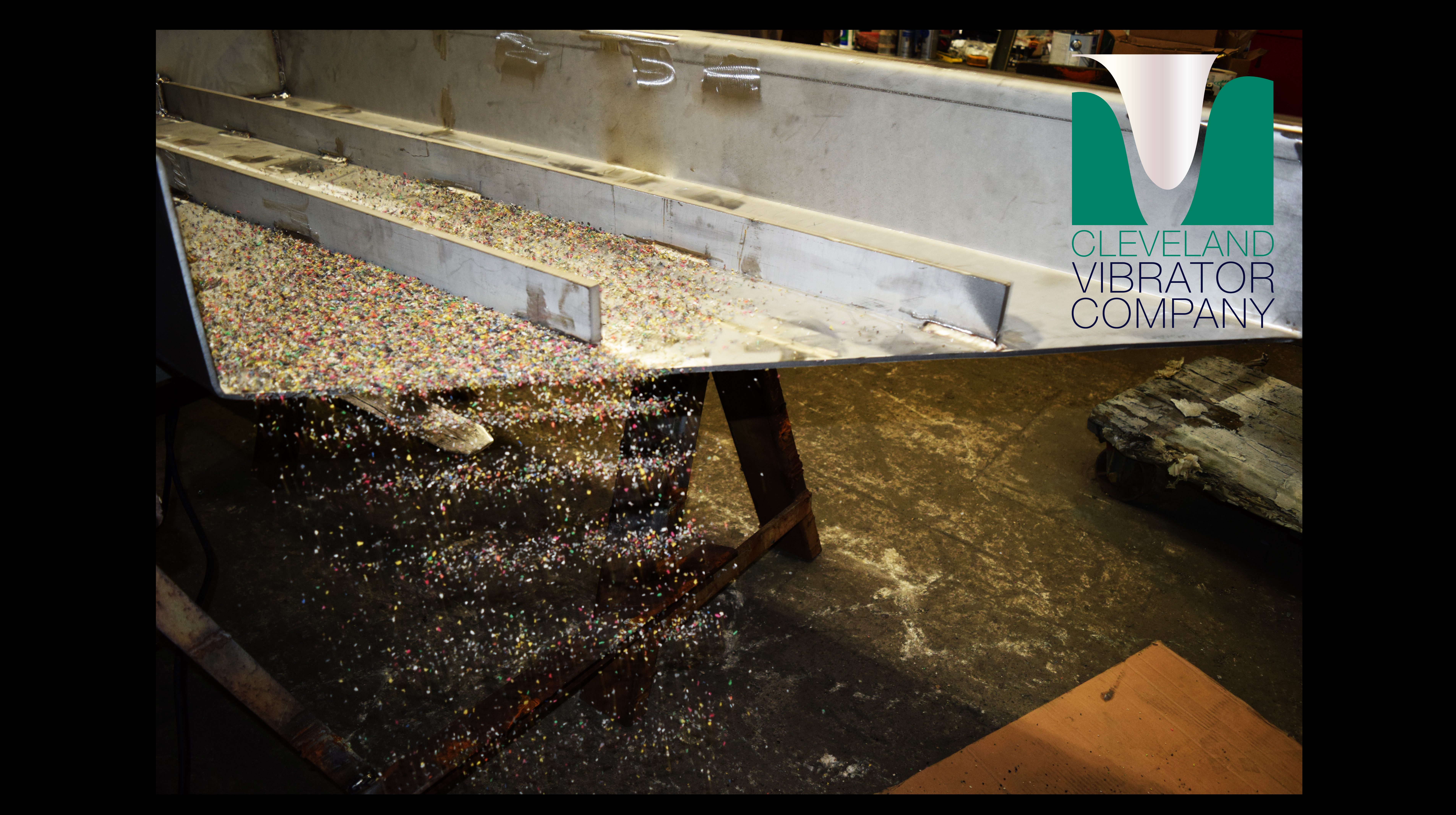
Working with a base mounted vibratory feeder (EMF) we set the unit up with the vibrators counter rotating. As you’ll see in the video the material moves quickly down the unit and discharges off the end, flow is even across the unit. Additionally, I demonstrate the “masking tape test” where we put a piece of tape on the side of the unit and touch the unit/tape with a pen or pencil. With the proper set up of the vibrators this procedure will result in a short straight line being made on the tape. The length of the straight line is the peak to peak amplitude of the equipment; the straight line is a result of the counter rotating synchronized rotary electric vibrators.
Once we’d videoed the proper set up we changed one vibrator and once again videoed the results. It is very clear in the video that material moves to one side of the unit and the rate of travel on the feeder tray is much slower than with the counter rotating vibrators. Repeating the “tape test” yielded only a small “dot” of a stroke, not the straight line that would be an indication of linear force being produced by the counter rotating vibrators.
Hopefully the video will give our equipment users a better idea of what to look for in the way of unit performance when they install and start up the equipment for the first time. The sooner the vibrators are properly set up the better for the performance of the unit. Even though a sticker calling for counter rotation of the vibrators is installed in the electrical junction box on all pieces of vibratory equipment with base supports, mistakes can be made during the wiring of the unit. In an effort to further reduce the opportunity that a unit will be set up with vibrators running in the same direction, I’ve written up some additional information that we’re now including in the installation and operation manual for our vibratory equipment. This information can also be found on the company website by following this link.
Certainly if there’s ever a question regarding the proper set up for a new piece of equipment, please give us a call, The Cleveland Vibrator Company is happy to assist.
Share this blog post:
Follow us: