Generally speaking, in life, choices are a good thing. This applies to industrial vibrators and vibrating equipment as much as it does for lunch time options. In terms of fabricated vibratory equipment, Cleveland Vibrator offers a variety of solutions to processing and material handling problems. Regardless if the need is for a vibratory feeder, screener, compaction table or vibratory belt table, our sales and application folks are up to the challenge of solving the particular needs and requirements of our diverse customer base. As I mentioned in earlier blogs, when it comes to vibratory equipment, one size in fact doesn’t fit all. Rarely do one customer’s particular requirements match up exactly with another customer’s, the solution may be similar in type but not in exact physical size. Tailoring to meet the individual needs of each customer is part of the Cleveland Vibrator fabricated equipment DNA.
One of the many types of fabricated equipment manufactured by The Cleveland Vibrator Company is the volumetric feeder. Internally, they are generally referred to as Hopper Feeders, RFM, these units can be pneumatic or electric powered. The key design element is that a vibratory feeder has a storage hopper associated with it which accepts and stores dumps of material and then feeds the material out of the hopper in a controlled manner. Read More…
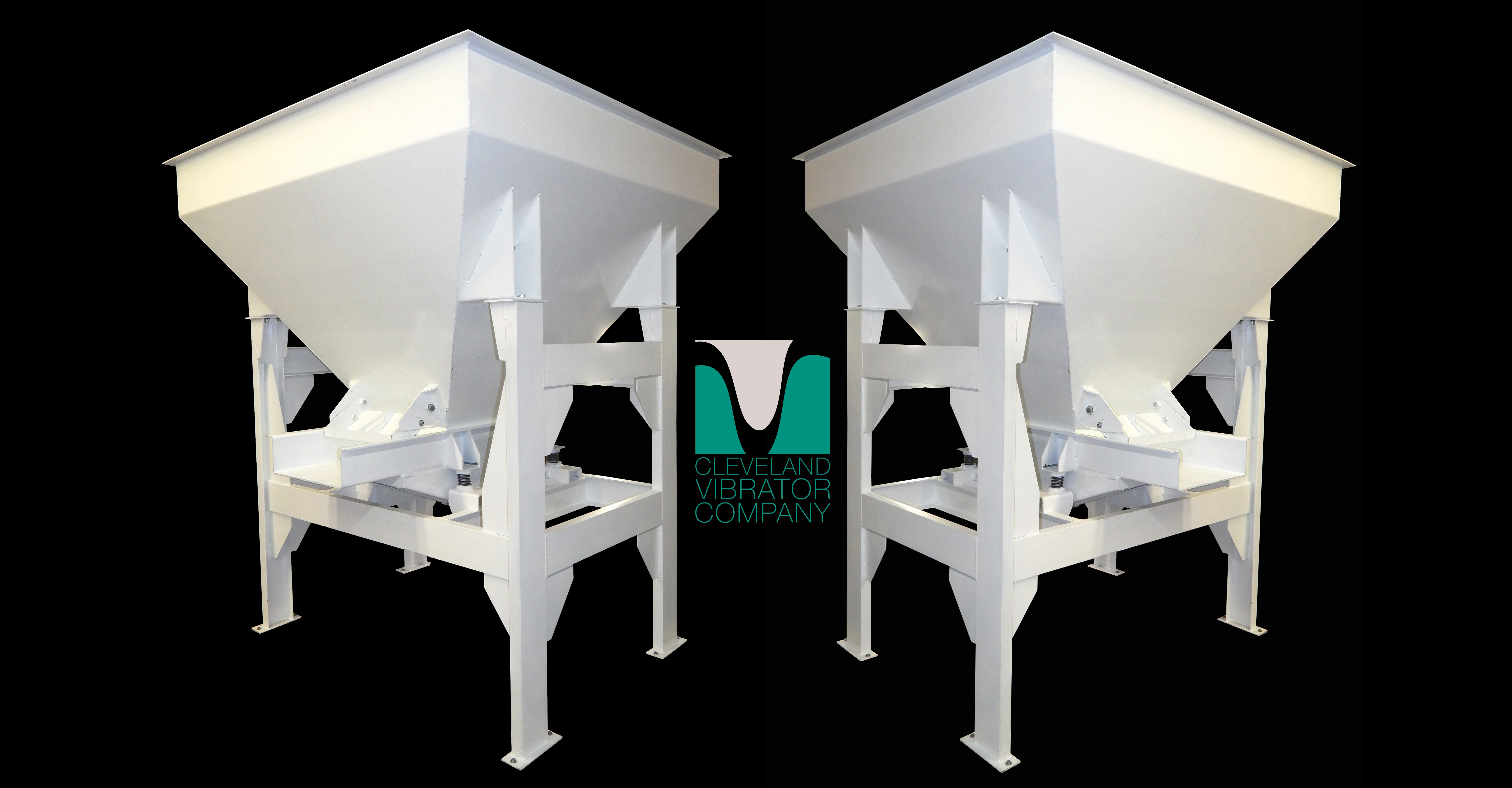
With a new exciting year in sight for me here at Cleveland Vibrator, I took some time to reminisce on some of my favorite FAB jobs that headed out of our facility throughout 2015. As I was perusing through my photo files, I found that our Vibratory Compaction Tables dominated this past year with our Vibratory Feeders running a close second. If you have read any of my other blogs, you will know that one of my favorite obligatory duties around here is filming equipment for quality assurance purposes before it leaves our manufacturing plant. Moreover, I love learning about new applications which our equipment will be used for and let me tell ya’, there were some pretty fun ones this year. So let’s take a trip down memory lane and get us stoked for the upcoming year folks!
At the beginning of last year, David Strong, Jack Steinbuch and myself took a maintenance visit to a customer right here in Cleveland to see one of our flat decks in the field. Read More…
I’m sure most of us remember the changeover push to convert our old standby of paper bags to plastic ones and how we somewhat resisted this at our local grocery stores. But as usual, with a little pushing from genius marketing gurus of our time, we eventually gave in and accepted the changeover. “Paper or Plastic” has pretty much disappeared to plastic only in today’s day-in-age.
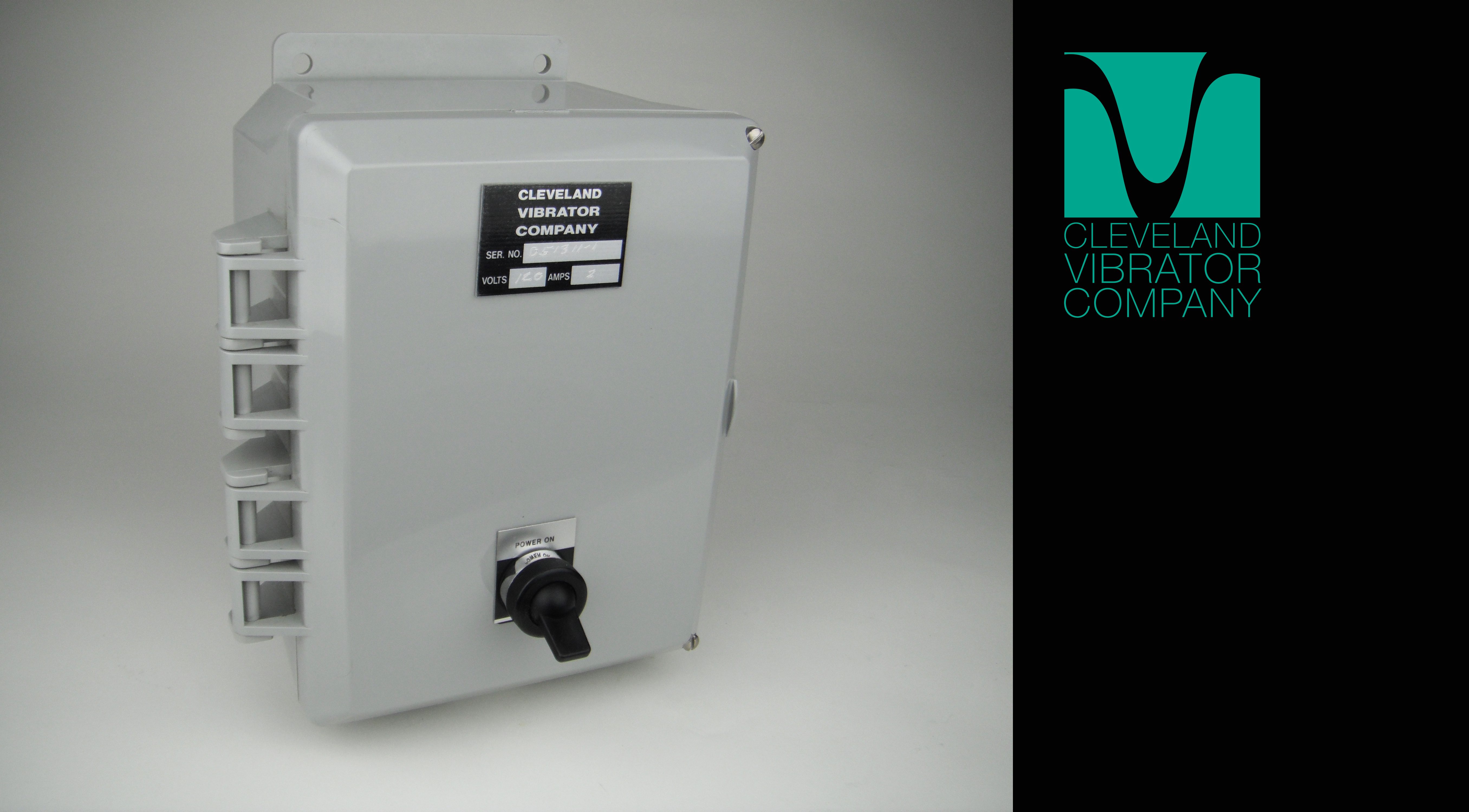
I believe we went through the same changes as it pertains to electrical controls for our electric vibrators and vibratory equipment manufactured by The Cleveland Vibrator Company. When I started at CVC in the 60’s, pretty much all controls were steel construction with the NEMA 4X being stainless and the explosion proof enclosures were cast aluminum. We carried several types of sizes of NEMA-rated enclosures in stock just to try and cover all the bases. The responsibility of our sales team was to identify the NEMA-rated requirements of our customer’s application. This at times was easier said than done of course. Purchasing was given the responsibility of having the enclosures in stock plus having suppliers who could deliver the enclosures in a timely fashion when we experienced an out of stock situation. Lastly, of course, our manufacturing team was given the task of manufacturing the many types of controls required by our valued customers. Read More…
Once again I’m touching on the topic of the proper setup of rotary electric vibrators (RE) when they’re used on vibratory equipment. Most of the vibratory equipment manufactured by The Cleveland Vibrator Company uses two rotary electric vibrators to produce linear vibration. Vibratory tables (FA), vibratory grid tables (GT), electromechanical screeners (EMS) and electromechanical feeders (EMF) are all designed for the vibrators to counter rotate. Again, counter rotation simply means that the vibrators rotate in different directions, one clockwise and the other counter clockwise. It doesn’t matter which vibrator of the pair rotates clockwise or counter clockwise, it’s just important that they both don’t rotate in the same direction.
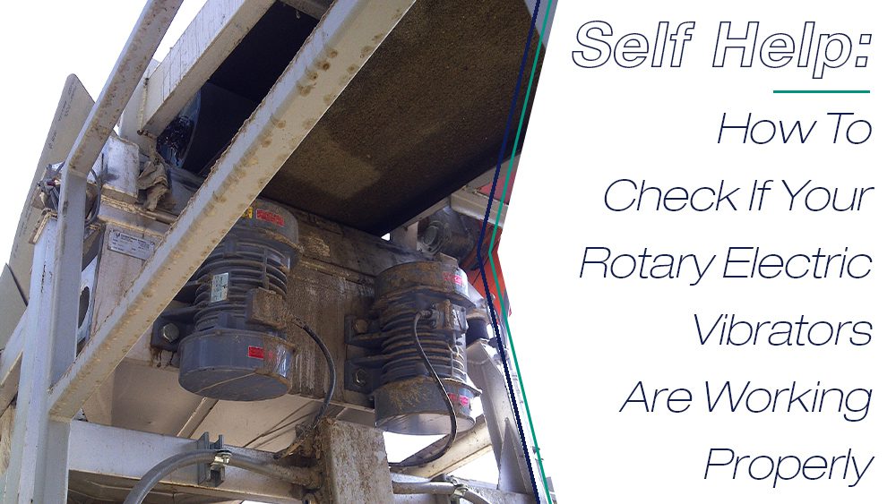
I recently tagged along with Jack Steinbuch on a visit to a customer who was experiencing some problems with a vibratory hopper feeder (RFM). After inspecting the unit we asked the customer to remove the weight covers on the vibrators so we could check the rotation direction. Once the weight covers are removed from the same end of each vibrator it’s very easy to see the direction of rotation as the vibrators are started up. At startup it was clear that the vibrators were NOT counter rotating as required. Read More…
Anyone who knows me well knows about my undying love for chocolate. I had a great aunt who lived 98 wonderful, rich years and was as quick as a whip until her final days… so what was her secret? A piece of good quality chocolate a day will let you live long and prosper. I will never forget that and have adopted that mantra. Since I began working at Cleveland Vibrator over 5 years ago (wow times flies!) I have seen how industrial vibration mixes with some of my favorite things in life. One of which, if you haven’t guessed already, is chocolate.
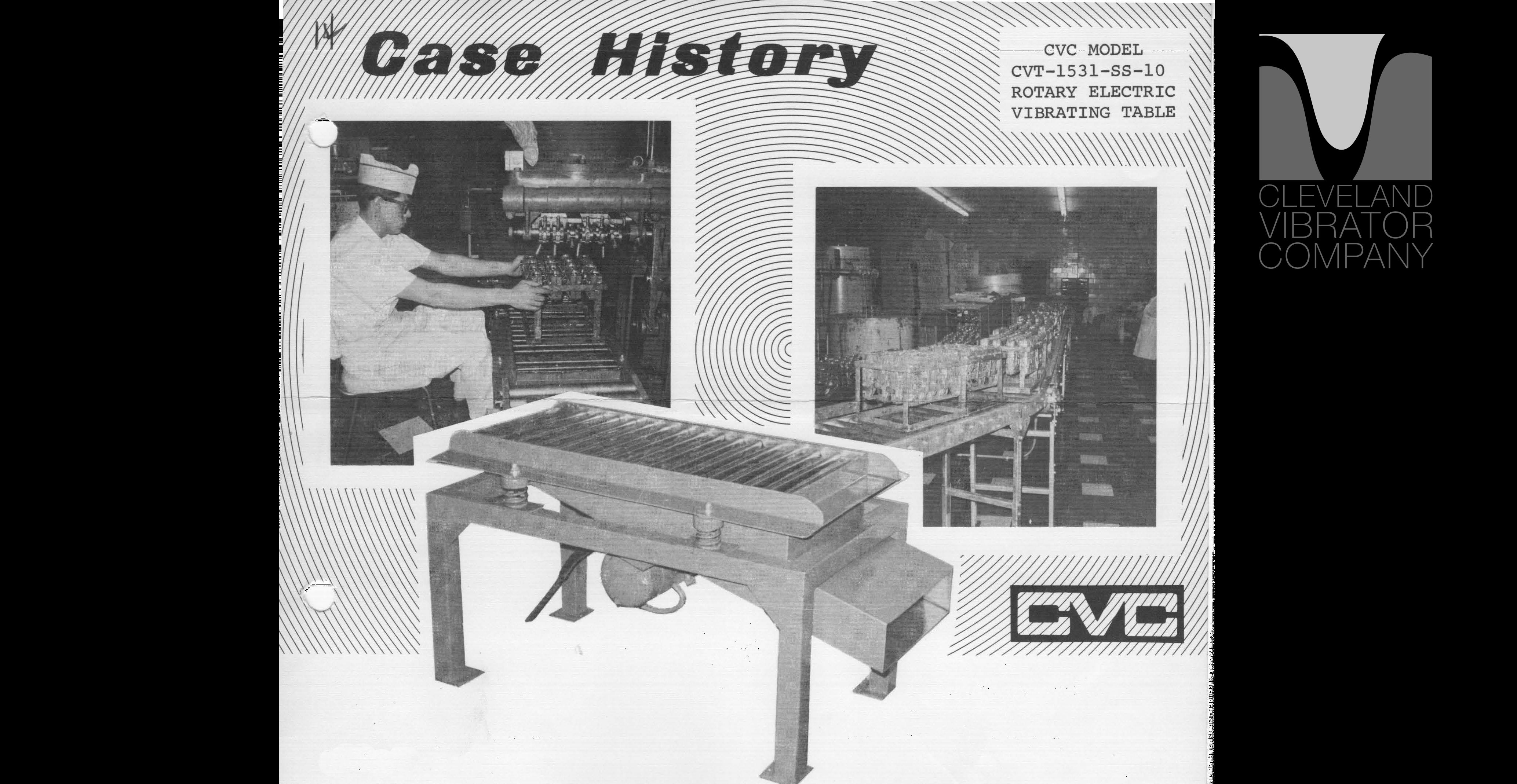
I was perusing through our case history archives last week and found one dating back to the 1960s where industrial vibration was being used in a leading candy producer’s factory. Their chocolate molding department was encountering an air bubble problem in their molds during the filling process, Read More…
Variable Frequency Drives (VFD) have become commonplace in many of our bulk material handling applications due to the adjustability they provide and the cost which has become more attractive over the years. However, I have found that many of our customers do not understand what they can achieve with this controller and how it affects acceleration when working with our electromechanically driven equipment featuring twin electric motor vibrators like our EMF vibratory feeders, EMS vibratory screeners and FA flat deck & GT grid top tables.
So we will start off with the fact that is contrary to what some might think – the lowering of the frequency does not affect the stroke being produced by the equipment. The stroke of the equipment can only be changed by mechanically adjusting the eccentric weight settings on the vibrators.Read More…
Jack Steinbuch retired in 2021 following a decades-long career with The Cleveland Vibrator Company, where he served as a Sales Engineer for more than 36 cumulative years. His background also includes extensive experience in the manufacturing industry as a Senior Application Engineer, and throughout his tenure with our team he contributed in both sales and managerial roles. Prior to his retirement, he held the position of General Sales Manager.
A graduate of The University of Toledo with a BSCE, Jack is highly regarded for his expertise in sizing vibratory screeners, feeders, and vibratory drives for tables and other equipment. Known for his dedication to customer service, he has always emphasized the importance of recommending the right solution for every application — even when that solution did not come from The Cleveland Vibrator Company.
Outside of work, Jack enjoys spending time with his family, especially his grandchildren. An avid sports fan and participant, he enjoys golf and spent many winters as a league bowler. With his retirement planned for the end of September 2021, Jack looked forward to spending future winters vacationing in Florida.
In a recent blog, we talked about the importance of “Counter rotation and synchronization” in the successful operation and maintenance of vibratory equipment. Now, we will touch on what you should do to properly adjust the eccentric weights on your rotary electric industrial vibrator. Although these steps are straightforward, they are crucial to the operation and longevity of the vibrator. Properly setting your eccentric weights can assist in keeping your equipment and vibratory investment free from damage. This is a great opportunity for us to expand on this subject, and, to be honest, we just LOVE spreading #VibrationEducation!
How to calculate vibratory force?
First, let’s delve into everyone’s favorite subject: Math. Understanding these concepts can help explain why setting your eccentric weights is important, and how it impacts your industrial vibrator and equipment. Any type of rotating vibrator, that includes rotary electric (RE), ball, or turbine vibrators generate their vibratory force by rotating a mass around the center of the unit or shaft. The force produced is dependent on three parameters:
Weight of the rotating mass
The distance of the center of gravity of that mass from the center of rotation
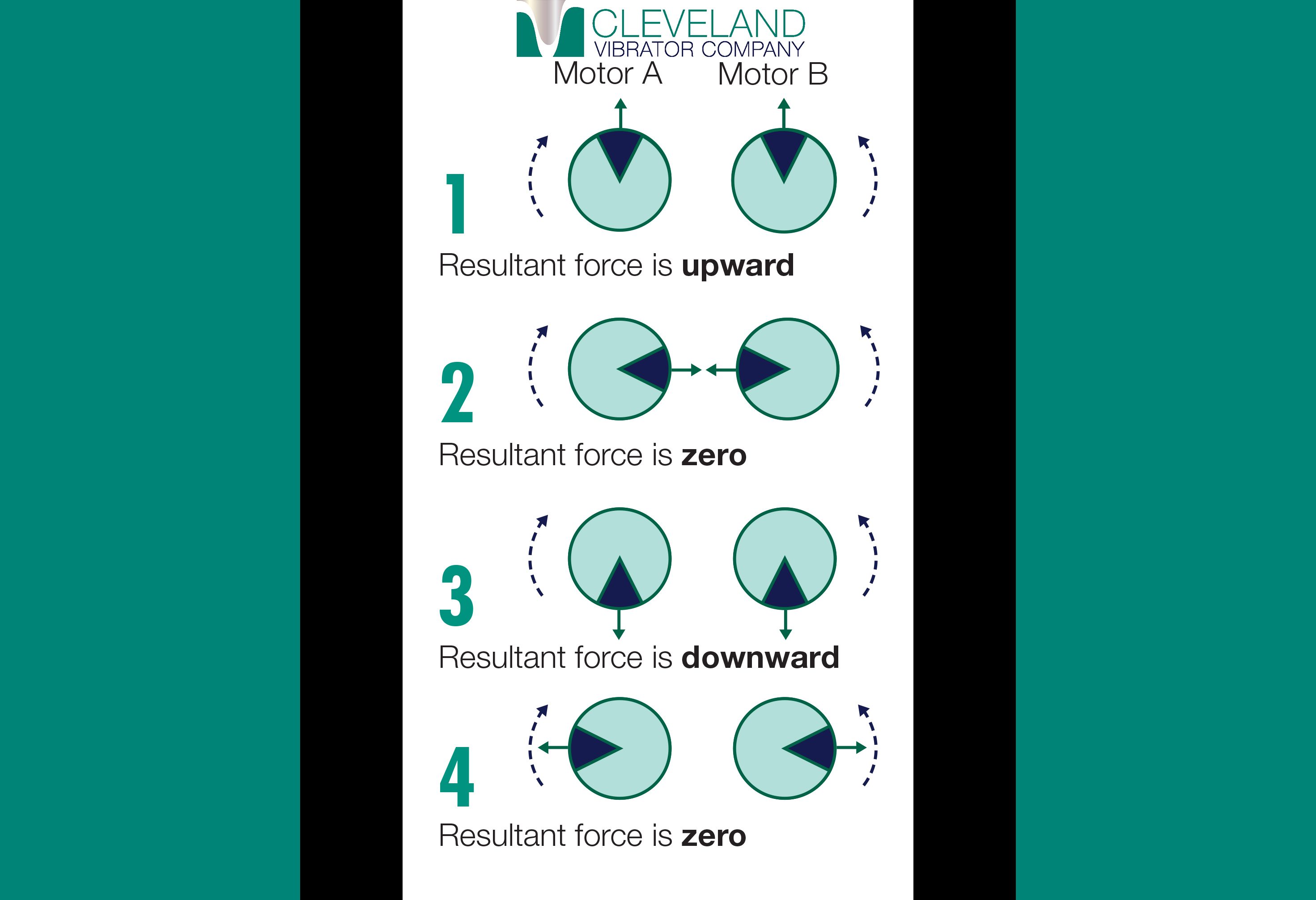
We manufacture a complete line of vibratory equipment. The product line includes a variety of vibratory table configurations, including flat deck, low-profile, grid top, and belt vibratory tables, along with Electromechanical feeders (EMF) and Electromechanical screeners (EMS). Many of these units are of the general “brute force” design type. This broad design category is based on the principles of counter-rotation and synchronization for two electromechanical rotary electric vibrators.
Counter Rotation of Your Rotary Electric Motors
Brute force units require the use of two rotary electric motors. When mounted to a rigid structure, the vibrators will “sense” each other and attempt to run at the same speed. When operated alone, a rotary electric vibrator will produce a rotational or centrifugal force. However, to produce linear force with two vibrators, the pair must run together and Counter Rotate. When mounted side-by-side and viewed from the end, one vibrator must run clockwise, and the other vibrator must run counter-clockwise. In typical applications, it isn’t important which vibrator runs in which direction. However, they must run in different directions.
When running properly and in opposite directions, the forces produced by the two vibrators cancel each other except for two times in a cycle when the eccentric weights of the vibrator both point in the same direction. With the Cleveland Vibrator line of three-phase powered rotary electric motors, changing the direction of rotation on one of the vibrators is as simple as “flipping” two of the power legs of the vibrator. Below, you can check out a diagram showcasing counter-rotation and force cancellation.
Rotary Electric Vibrator Force Cancellation
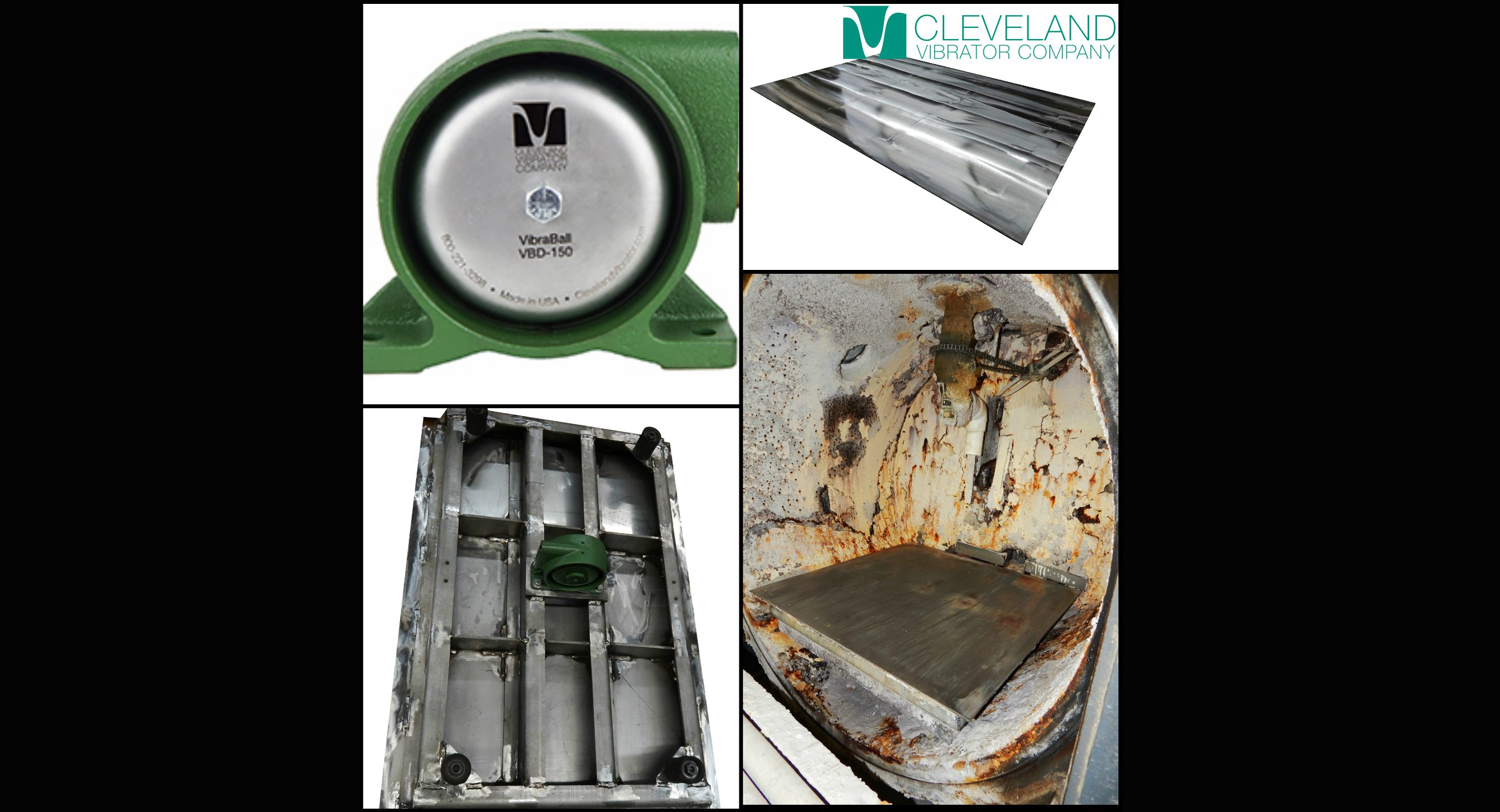
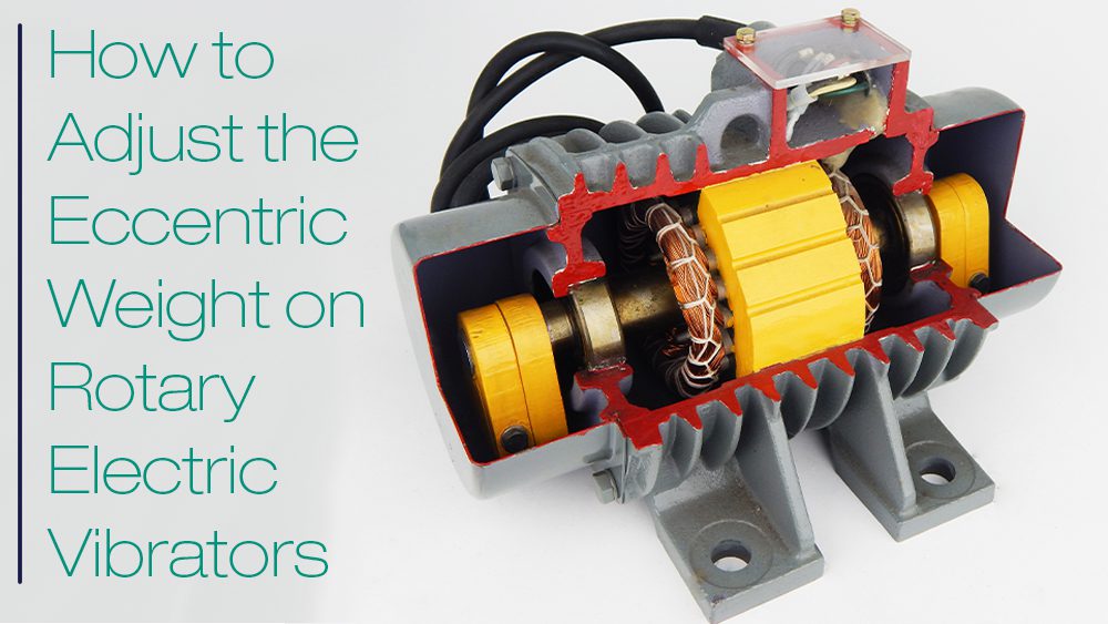
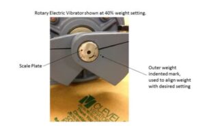
For the sake of completeness, let’s take a moment to discuss the design of the rotary electric vibrator. Very broadly, the rotary electric vibrator is a through shaft motor with bearings on each end of the shaft. Outside of the bearings, two eccentric weights produce an “unbalanced” condition when the motor runs. This unbalanced condition produces the vibration used to move, screen, or compact a variety of products. The eccentric weights are “pie-shaped” and are clamped onto the shaft with a bolt. The eccentricity, or unbalanced condition, of the motor can be varied from 0 – 100% based on the relationship of these weights.
Adjusting the Eccentric Weights on Your Rotary Electric Motor
To access the eccentric weights, remove the four bolts that hold the weight cover in place. Then, remove the weight cover. The outer weight, the one furthest from the center of the vibrator on each end of the vibrator, can be rotated to a new location changing its relationship to the inner weight. This adjusts the unbalanced condition, thereby increasing or decreasing the force output of the vibrator.
Never change the location of the inner weight; only adjust the outer weight. If one outer weight is changed, then ALL outer weights on both vibrators must change.
On each end of the motor shaft, you’ll see a dial with increments between 0 and 100 percent. The outer eccentric weight has a small “punch mark” or “dot” on the face of the weight. The punch mark is aligned with the desired weight setting on the dial. See the photo to the left, which shows this “punch mark” with the dial set to 40%.
Counter Rotation Example
If the goal is to reduce the force produced by a vibratory table, the customer might decide to “turn the weights back”. In other words, change the position of all outer weights to say 40%. All four outer weights are rotated so their punch marks align with the 40% mark on the dial on the end of the shaft. The unbalance of the vibrator is reduced by changing the relationship of the inner to outer weights. This also reduces the force it produces at any given speed.
On a piece of equipment, it is critical to the success of the operation and the serviceable life of that unit that all outer weights on each end of both vibrators are set in the same location. Refer to the rotary electric manual or call us if you have any questions. It’s crucial that all weights are properly set.
Rotary Electric Vibrator Synchronization
Once the outer weights are set the same and the rotation has been checked to confirm counter-rotation, the unit can run and the vibrators checked for synchronization. Synchronization simply means that the vibrators are running at the same speed in opposite directions and thereby producing linear vibration. When supplied by us, typical controls for equipment are either a magnetic starter or a variable frequency drive (VFD). They must start together and be controlled by one starter device.
While doing a final check on the equipment prior to shipping, we will periodically check for synchronization of the vibrators. To check for synchronization, one weight cover is removed from each vibrator exposing the two eccentric weights on the same end. Once the covers are removed, the unit is restarted and run. Use caution when operating the vibrators with the weight covers removed.
While the unit is running, a strobe tachometer is used to “stop” the motion of the rotating weights. This allows you to check to see that the vibrators weights are a “mirror” of each other. To “stop” the motion of the vibrators, adjust the frequency of the strobe to match the operational speed of the vibrators. At the operational speed, the motion will appear to “stop”. Now you can easily observe the relationship of one set of weights to the other. You can see this process in action in the video below.
In the video, the initial frequency of the strobe was slightly off that of the motors. As the speed of the strobe approaches that of the vibrators, the two sets of weights appear to slow to a “stop”. As seen in the video, the orientation of one set of weights should be mirrored onto the other vibrator. When the weights appear to “stop” and the orientation is observed, the position of the weights should be a mirror copy of each other. If this is not the case, then the vibrators are not synchronous and will not produce linear motion. This is not the desired condition for successful operation for vibratory equipment utilizing the brute force design.
What does it mean if the vibrators are not running together in synchronous operation?
This could indicate a problem with one of the vibrators, perhaps an early indication of pending bearing failure or lack of grease on the vibrators with grease fittings. Please refer to the operation manual for the recommended maintenance schedule for grease application, both quantity, and type of lubrication. Some of the smaller vibrators are permanently lubricated and don’t require maintenance of this type. Another option would be to double-check the tightness of the vibrator mounting bolts. As discussed in the maintenance manual, the vibrator mounting bolts should be checked periodically for tightness. Loose bolts can prevent proper operation and synchronization of the two vibrators.
If you have any questions, our friendly and knowledgeable Sales and Services Team is here to help. Contact us today!
Now that we are past Memorial Day weekend, and thank you to all that have served, are serving or will serve our country, the summer months are upon us. For some, and depending where you live, these are the best parts of the year, namely, because of the warmer temperatures. While we enjoy the extra hours of sunlight and are exposed to more vitamin D, Mother Nature can have a serious effect on manmade structures. This is certainly the case for Texas and Oklahoma right now as many cities in this part of the country have experienced record rain falls for the month of May. This amount of rain can often be attributed to the rise in moisture content within the atmosphere.
Mike joined The Cleveland Vibrator Company team in 2013 with prior experience in manufacturing sales with a Cleveland company in the tool and die industry. Now, he’s the Director of Sales and specializes in “making stuff that shakes stuff”.
When he’s not immersed in the world of industrial vibration, as rare as that might be, Mike keeps busy *not finishing in last place* in Fantasy Football and enjoys spending time with his wife and three kids. It’s always golf season for Mike, and he’s been known to 3 putt his way around any course and can roll tee balls in rain or shine. You can find him tailgating in the Muni Lot before Browns games or supporting local breweries.
As an avid provider of #VibrationEducation, he offers this free bit of advice, “Not all vibration is the same. Force and frequency do matter!” However, there is a 2% upcharge for all Michigan and Steeler’s fans.
Powder coaters know the importance of utilizing a powder coating that is free from any contaminants or oversize particles. This would include the end-user and the powder coating manufacturer. Typical powder coating applications can leave up to 20% of the original powder either to be recycled or swept up and thrown out in the trash. Depending on the application this can be like throwing money out with the garbage.
Over the years we have built numerous vibratory check screeners for the powder coating end user who is interested in reclaiming the excess powder left over from a product run. Typically powder coatings are sieved in the 80-120 mesh range by the manufacturer. This mesh range is dependent on the type of powder and application where the powder is applied. When a customer approaches me with an application involving powder coating reclaim, I first inquire about his application. Is the finish a high-quality finish or coating possibly for a protective value? Secondly, is this a continuous or batch operation? This helps in determining the proper mesh size. High-quality finishes require a finer mesh size while other finishes may require a coarser screen. Both will remove the contaminants inquiries range from reclaiming powder swept up from the bottom of paint booths, while also protecting applicator spray guns from blockage. Read More… Share this blog post:


