
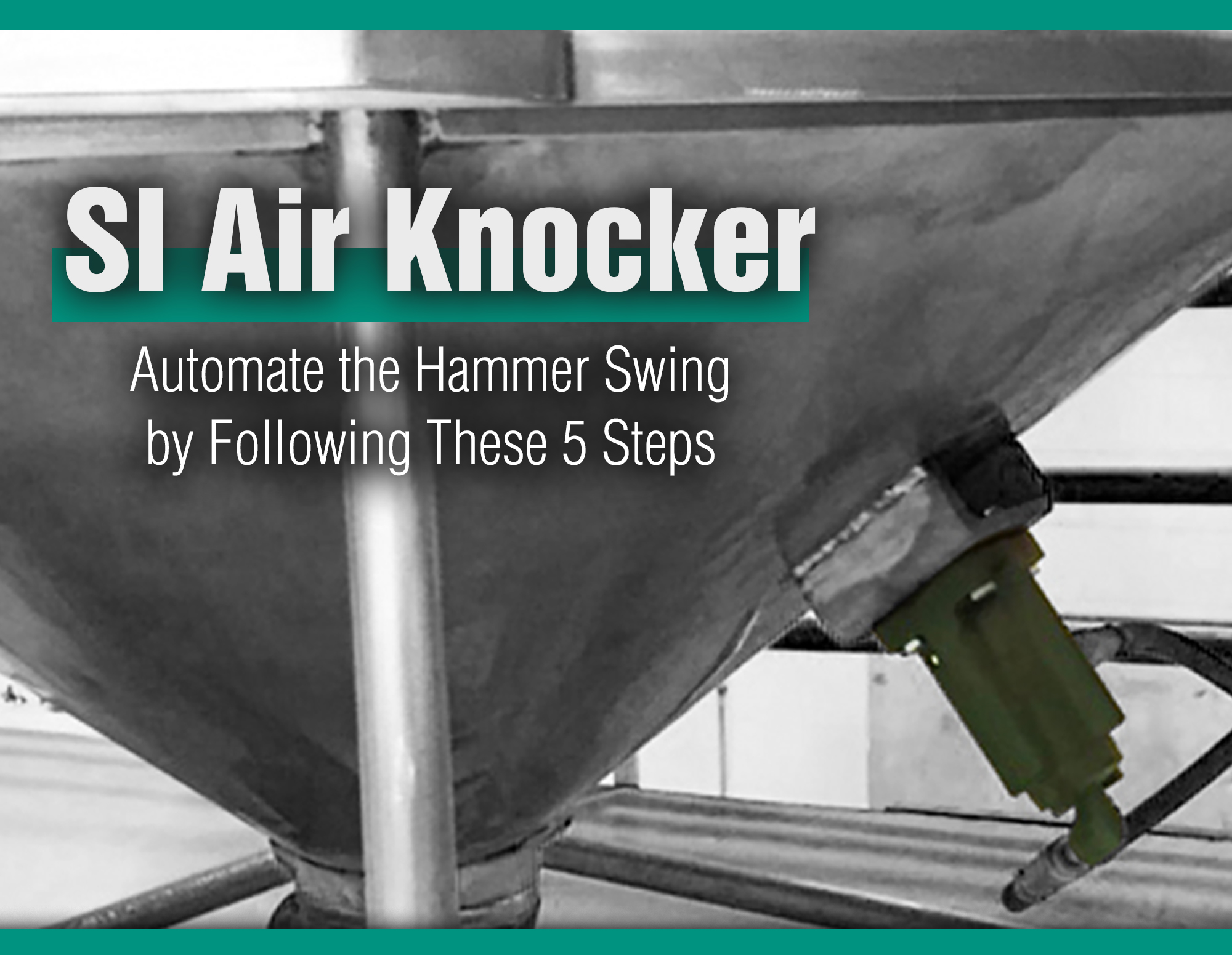
Our team is frequently asked about the proper installation of our Single Impact Air Knocker units. Since these units require two strokes of air for proper operation, the required components and installation process are slightly different than a more traditional pneumatic piston vibrator. Here, we will answer frequently asked questions and walk through the step-by-step installation process.
Step One
After properly sizing and selecting the units (which can easily be completed by utilizing our Vibrator Selection Guide!), it is time to install. First order of business, what are the components required for proper operation? There are a few items needed:
- The Single Impact Air Knocker (Complete with the Exhaust Port Protector and Grade 5 mounting hardware, provided with each unit)
- The Mounting Channel
- Hoses
- Valve
- Filter/Regulator/Lubricator
- Safety Cable
- Timer Box (Optional)
When it comes time to get the air knockers on the bin, hopper, dust collector, etc. there are a few tricks to keep in mind for the proper installation. Remember, vibrators don’t damage equipment, poorly sized and installed or operated vibrators do.
When complete, we will want the installations to look like the example to the right, courtesy of Seed Processing facility.
Step Two
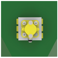
Next, stitch weld the mounting channel to the exterior wall of what is being vibrated and weld a bracket to use for the safety cable assembly. See picture above for safety cable installation example. To the left is an example of the mounting channel install, the yellow stitches are the welds.
Step Three
Once that is in place, we will want to get the SI Air Knocker unit bolted to the mounting channel. We provide Grade 5, Fine Thread fasteners with Lock Nuts on each unit we ship. Saving the installer time and money by not having to go searching for the correct hardware. Then we will make sure that the Exhaust Port Protector, also included with each unit, is threaded into the exhaust port. This may seem simple or like something not needed but it is very important. It keeps the Air Knockers sealed and prevents dust, dirt, water, or other contaminants out of the casting of the unit.
Step Four
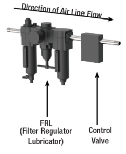
After that, we will want to look at installing the air prep components: The Valve, and the Filter/Regulator/Lubricator. We suggest that the FRL is installed upstream of the Valve. This will get the properly filtered air regulated to proper operating pressure (between 20 – 80 PSI) before being lubricated. We want the Valve lubricated as well because there is a piston inside the Valve that slides back and forth and lubrication is needed for the air controlling the impact and return strokes of the piston inside the Air Knocker.
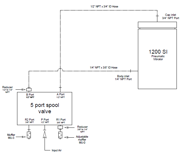
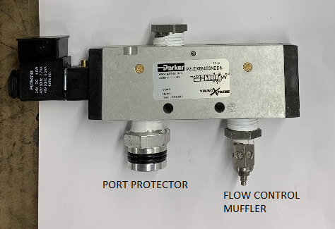 The Valves needed for operation are 5-ported to send two strokes of air to the Air Knocker. Below is a hose schematic showing how the air lines are plumbed between the SI Air Knocker and Valve. It is critical to know which of the five ports on the Valve get hoses and which get mufflers. To the right is an image showing one of the Valves in assembly.
In a perfect world, we want the air prep components to be within 10 feet of the installation location of the Air Knocker.
Step Five
Now that we have the Air Knocker bolted to the Mounting Channel and Safety Cable Assembly in place, the Hoses connected to the Valve and Filter/Regulator/Lubricator, it is time to look at controlling the unit. If the unit is being controlled by a Valve with a solenoid head where an electrical signal is 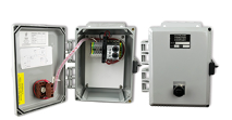 required for operation, we can provide a Cycle Timer Box (pictured to the right), or an onsite PLC can send the signal to the solenoid on the Valve. Here is a video showing how the Timer Box and Valve with solenoid are operated.
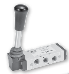 If the unit is operated with a Valve that has a lever for manual operation and no electrical connections, then the Timer Box is not required. Rather, an operator must manually flip the lever on the valve for operation. To the right is an image of the Lever Valve type and here is a video showing it in operation.
After these five steps, there will no longer be the need to manually hammer bins! Who doesn’t like a little bit of automation these days? Not to mention the damage it will prevent to your equipment, and the backs and shoulders of your employees.
We hope this helps answer some questions! If not, or if there are other questions, feel free to reach us at sales@clevelandvibrator.com.
Follow us:
Share this blog post: